
 EN
EN  Ελληνικά
 Deutsch
 Français
 Español
 Italiano
Self-holding contactor circuit
The self-holding (latching) circuit lets a momentary Start button energise a contactor that then keeps itself energised through its own auxiliary contact, until Stop is pressed. It is the basis of almost every motor control circuit.
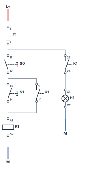
What you will build
A 24 V DC control circuit: fuse F1, stop button S0 (normally closed), start button S1 (normally open) in parallel with the holding contact K1 13-14, the coil of contactor K1, and a second branch with contact K1 23-24 and indicator lamp H1.
Steps
- New sheet. Open the app, click New → Blank drawing.
- Supplies. From Supply place L+ at the top and M at the bottom (choose the type in the properties). Points with the same name are connected, so you can place M twice, one under each branch.
- Fuse. From Protection place a fuse under L+. It is named F1 automatically; leave 6 A.
- Stop button. From Operators place a push button and set its contact to NC in the properties. It becomes S0 — rename it if needed.
- Start button. Place another push button, NO, below S0: S1.
- Holding contact. From Contacts place an auxiliary contact NO next to S1 and give it the name K1; its terminals become 13-14.
- Coil. From Relays & timers place a relay coil below: K1 (24 V DC).
- Wires. Drag from terminal to terminal: L+ → F1 → S0 → S1 → K1 coil → M. Connect the holding contact K1 13-14 in parallel with S1 (same two nodes).
- Lamp. Place a second auxiliary contact named K1 (it gets 23-24) from the node after S0, then a lamp H1 (24 V DC) from Signalling, and wire it to M.
- Check. Click the design check button: it should report no unconnected terminals.
Simulate
- Press
F5. Nothing is energised yet; S0 is closed, S1 open. - Click S1: coil K1 pulls in, contacts 13-14 and 23-24 close, lamp H1 lights. Release — the contactor stays on through 13-14. That is the self-holding.
- Click S0: the circuit is interrupted, K1 drops out, the lamp goes off.
- Try a fault: wire L+ directly to M on an empty part of the sheet and start the simulation — F1 blows and reports the short circuit. Click the fuse to replace it.
Why does Stop come before Start? If the holding contact were in parallel with both buttons, Stop could never interrupt the circuit. The NC stop button must be in series with everything that keeps the coil energised.
Variations to try
- Replace the relay coil with a contactor and add its main contacts in a power circuit with L1 L2 L3, a motor protection breaker and a three-phase motor.
- Add a thermal overload relay with its 95-96 contact in series with S0.
- Do the same with a PLC: S0 and S1 on inputs, K1 on an output, and the self-holding in Ladder — see PLC and Ladder.